Focus is very important for your work, if you are out of focus you will lose power or get strange effects when engraving.
This is the most common issue with new users on the k40 machine, the information from the seller how to use the k40 is very limited so this information is not there and a new user tend to search for other problems causing it, when it´s actually the bed and focal distance doing it.Lens setup calculator
Check out this calculator that helps you set up your lens and distance properly for engraving and cutting.
So, what is focus?
You laser tube has a beam aprox 3-5mm thick bouncing around the mirrors and hitting the lens.
The lens pulls the beam into a focus point in a shape similar to a hour glass.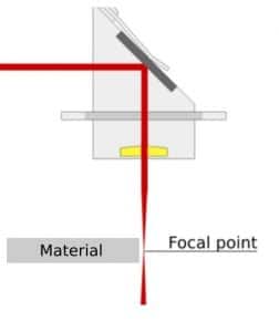
This image shows a easy picture of how the beam looks like in your machine. The thinnes part of the beam shape is your focal point where you should place your material for engraving or cutting.
When engraving you work at the surface, and should then have the focal point at the surface, but on cutting having it in the center of material thickness to keep the cut edge straight.
A leaning edge on a cut is evidence of wrong focus.
Why is proper focus important?
If you have the material too high or too low, the dot size will affect the outcome, for cutting you might get very charred edges, slanted edges or wide cuts. When engraving you get wider beam with less details in your engraving.
Identifying your focus
The K40´s arrives with a 12mm lens with a focal point of 50.8mm
This means the smallest dot is aprox. at this distance from the under side of your lens.
Make a piece of plastic, tooth pic or similar in 50.8mm length and put it against the under side of your lens and see if your bed is in proper height or not.
Or download a lens step-tool here, cut it in acrylic.
If you cannot stand the 50.8mm tool up, your bed is too far up. If you have space between the bed and the tool, your bed is good – for now.
To find the best focal point the ramp test is a good option – more about that later in this article.
The rounded surface has to be up – double check the orientation on your machine.
Moving your bed
If your test earlier showed that you had more than 50.8mm between under side of the lens and the bed surface, you can skip this step.
The K40´s are made different, not all of them are the same but take some photos of your machine to remember how everything went in, and remove the bed and inspect how your´s is fastened to the machine.
Most users, you, are engraving or cutting on material up to 10mm thick, so i usually recommend putting the bed at a height of 65mm from the lens underside and use scrap pieces to put your material into proper height – read more about this below.
Some beds stands on standoffs, some beds are fastened with L-brackets to the gantry.
Solving this has different approaches, but cutting the legs is one solution, or swap it out for something else holding the bed up.
Here is a picture from one of my machines. I have installed L-brackets on the side of the gantry holding a L-shaped frame as a bed. This is one example of how to mount your bed.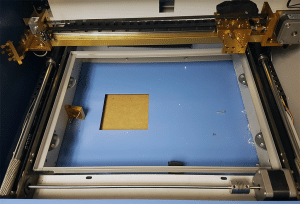
How do i set proper focus?
The K40 machines has one big flaw, and that is the bed.
When you get the machine, proper focus is inside the spring clamp in the bed. Anything you put on top of the bed will be out of focus.
Use the tool you made earlier, in this example i will refer to the tool i have in the download section, i recommend cutting one to use. Please note, it will only work with the standard K40 laser head without any nozzles attached.
For engraving
Use the tool you made earlier, in this example i will refer to the tool i have in the download section, i recommend cutting one to use. Please note, it will only work with the standard K40 laser head without any nozzles attached.
Put the tool under the edge of your laser head on the highest step – use scrap pieces below the material until the surface of the material is touching the bottom of the tool.
If you cannot fit the tool – you need to lower your bed.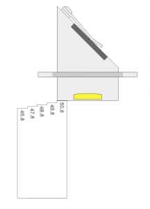
For cutting
Use the tool i linked to earlier, depending on the thickness of the material you want to cut you need to use proper step on the tool.
Ideal for cutting is to place the focal length – 50.8mm – in the center of the thickness of the material.
If you have 4mm acrylic, you want 50.8, minus half (2mm) = 48.8mm between material surface and lens under side.
Use the tool, and set the step with 48.8 engraved on the under side of your laser head and use scrap pieces to move the material you want to cut until it touches the tool.
If you cannot fit the tool between the head and material, you need to lower your bed.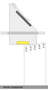
A word on movable beds
There is very common for users to DIY their own movable beds with different solutions, everything from gears and motors to scissor-lifts.
I tend to stop users from this, as the focus is very important one millimeter out will have a effect on your final result.
Installing a movable bed is a lot of work, you need to make it stable so it wont tilt with load on it – and make sure it keeps level in all positions, in all four corners at all times.
Most scissorlifts are very sloppy and putting anything on the bed in one side will tilt the bed really bad. But if you find a good one, use it but make sure its level and remember if you see any troubles not cutting through on one side, or faint engraving on one side – it´s probably your moving bed playing with you 😉
Before installing a movable bed, please make sure your machine is set properly on focus and you have learned how this works before you add more functions (problems) to your machine!
Ramp test
A ramp test is a angled piece of material on your bed to find your optimal focus.
I usually do not recommend this, because the bed in a standard K40 is too far up, the ramp test will not show a proper focus point.
If you want to do a ramp test, make sure you lower your bed enough to get the full hourglass shape of your line.
Bravo Technologies has made a great video explaining how to do the ramp test.
https://www.youtube.com/watch?v=iKpONnJru1w

Hi, I recently replaced my tube. It was no longer powerful enough. Since the new tube I have a problem with blurry engraving. Lens is in focus and it cuts perfectly. but engraving is blurry. Do you know how this could be.
Remember that engraving and cutting demands different spacing between lens underside and material surface. Double check with this calculator first: https://k40.se/k40-laser-calculators/k40-laser-machine-lens-focus-calculator/
Thanks for your Reply. Your site has been an important source of information for me for 2 years now.
Hy there! thank you for all your info!
I have a k40 laser and i use it with k40 whisperer, it’s new, never used before. when i engrave i get this wierd dotted background on stamps.
Any idea? Thank your very much!
Try the same thing with a piece of wood or thicker paper, lower the power.
If you get a smooth engraving on wood, its the stamp material racting and causing the dots, and you might need to play a bit with power and speed to make them go away.
Hi HP
First thanks a lot for your website that spared me a lot of headache .I have a K40 mirrors aligned bed right ,focus good …only one problem .When i engrave a plate 300mm /100 mm ….in the middle of the plate is out of focus with blurry engraving (only 2cm zone ) the rest on the sides is really nice and sharp .i can not think ehat is going on .Maybe you can help me ?
Kind regards
Razvan
Inspect mirrors and lens for smudges or damages, you can do a test – Rotate each mirror a halft turn, just turn the clockwise half turn, and see if the spot where it gets blurry moves.
If it does, your issue is with the mirrors or lens.
Thnks! i downloaded the file lasergauge ,however, it doesnt print any lines, like i see on the video.
i’m not very technical.. maybe i’m missing something.
help wil be appreciated, i’m trying to engrave aluminium canisters, however, ir prints on wood, but not the alluminium.. thats maybe because of the focus, maybe i put it to high..or to low
To be honest, i have not made much metal engravings at all. But what i have tested i always needed a marking solution to put on the metal to make it mark properly. Check google for “co2 laser metal mark” and you will find some products for this.
Or google on “cermark” to find more info.
Sorry for my limited knowledge here, but i dont think this is a focus or power issue, you probably need the marking solution!
Thabnks alot, i will search for it!
Very informative Thank You Sir!
Hi HP,
I am waiting for the delivery of an Adjustable laser head kit with air assist – 12mm that I bought from your store. My question is how do I install the lens on the Head. With the concave face facing up or down?
Rounded side up, flat side down. Put in the lens first, and the oring on top of the lens and tighten it just so the lens is held in place and cannot move, if you over-tighten it you might press the oring so you hit it with the beam.
Mine seems hard to line up as it keeps making cercles how can i stop that?
Is the beam making a donut instead of a dot? that might be a edge-hit on a mirror earlier, or hitting inside the laser head. Test with a paper directly in front of the laser tube to see if you get the same shape, then move to mirror 2 and before the head to see where the shape is created. If its out of the tube, it can do this on very low power, increase power a bit.
Hi Persson, I’m having the following problem with the X axis. When I cut a straight line of 19cm the laser cuts a line of 20cm (adds 1cm). Same problem with the Y axis, it add 0.50cm.
I understand that this is solved by changing the steps over software and send it to the controller, but I do not know how to do it. I see some videos doing that but with another (SOFT and Controller).
Do you know how to Fix that on K40?
Best Regards
Juan
Great informations with the widio from techbravo. one point I don,t understand. I hve a std. 40K maschine. In the test he made with 4 lines, he said, that he made 1 line 10 – next 20 – next 30 etc in effect /amp. How is this done – doing severel different effect in same picture ?????
He either uses a cohesion3d where he can set the power from the software, or just increase +10 on his digital panel for each line manually.
This may be nit picky, but you mention measuring from the underside of the lens,
Since the laser beam starts to bend at the top (curved surface) I interpreted this to indicate that the 50.8 mm is from the top of the lens.
Do you agree? Since the lens is around 2mm thick, that difference could change the distance from the lens,
I am particularly interested in this as it relates to my current project of rearranging the optical path a bit.
Agree, the beam starts to “form” in to the focused path/form in the top, but it´s not done doing so until it leaves the lens on the underside. The thickness is a factor of the lens function. We did some heavy testing on this in a Wyko optical profiler, bad lenses had the shape formed (completed) a mm above the underside and gave really strange and short hourglass-shapes as the last mm of the lens distorted it. Hard to explain without pics 🙂 But, a ramp test might help you find that last millimeter of sweet spot. If the deviation is too great, upgrade your lens.
I have made a 3D model of the gauge wich can be downloaded here. I have added 49,3mm and 50,3mm for material of 1 and 3mm thickness.
https://www.thingiverse.com/thing:3038024
Nice work!
Although it is clear from your diagrams it is probably worth stating explicitly that the curved face on the lens must go to the top with the flat face at the bottom.
Good point! i have added a little info-box with this info now 🙂