We have all seen it – strange cables going from anywhere to nowhere and back again.
The K40 is a potent little machine and with this guide we show you how to rewire the machine from the ground up with every detail you need.
Parts and tools you need
– 0.75mm2 cable for the small 12 and 5V connections
– 1,5mm2 cable for the high voltage wiring. Make sure to choose something rated for at least 250V.
– Wire strippers, cable crimpers and screw drivers.
– Crimps, spade and ring terminals.
– Cable sock or cable protector from nylon or similar material.
– Soldering iron – for better connection on the crimps.
– A cold beer or other drink
– EMI-filter – highly recommended!
Preparations
Take out a pen and a piece of paper. Make notes of your current setup what cables goes where. Not all K40 laser cutters are the same and you can have one of them with strange wiring inside.
Only use your notes as reference as this guide will tell you how to rewire your machine properly and in a safe manner.
Take some photos of the cables and save it, if you do something wrong it´s good to have if you need to revert back to your old setup.
The K40 laser cutter machine has two types of PSU´s
We will describe both types in this guide as they are very similar.
First step – laser tube and high voltage
Before doing anything – make sure the power cable has been pulled out from the machine at least a few hours.
Laser tube check: Follow the negative cable from the laser tube to the PSU – it should be located on the L- connector. If not – move it!
In the rear of your machine you have a bolt going through the metal with the ground wire connected from the C14 inlet connector.
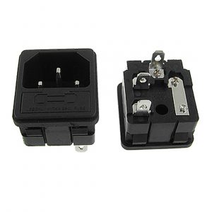
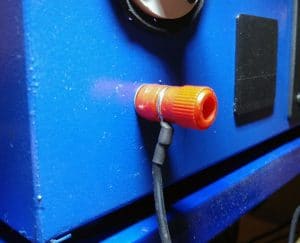
Remove the ground bolt and remove the cables from the C14 connector.
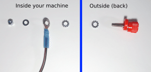
Clean the metal around the ground bolt and mount it back without any plastic washers, you need good proper connection between the bolt and the metal case.
High voltage wires
Here is my example of a high voltage rewire kit with a EMI-filter.
The lose ring terminal goes to the ground bolt shown above.
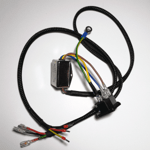
The length of the cables depends on your machine and your PSU location. Take a piece of cable and measure how long pieces you need.
In this example the length needed from the rear C14 connector to the lid power switch is 40cm, and from the lid to the PSU is 30cm.
Types of crimp terminals used

Wire ferrule crimp connector
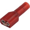
Female “disconnect” type terminal (suggest a better word in the comments please 🙂 )
Wires needed
2x of 40cm wire (black and red, or other colors just make sure you know which is which)
3x of 30cm wire (black and red)
1x of 70cm wire (yellow/green for ground)
Crimps needed
2x 30cm wires needs to have the female disconnect crimp in one end and ferrule crimps in the other end.
2x 40cm wires needs female disconnect crimp in one end and the other end connected to the EMI-filter live pins.
1x 70cm ground wire with the ferrule crimp in one end and the other end connected to the EMI-filter ground pin.
Chart over the cable kit we just made
Installing the cables.
The two 40cm wires and the 70cm ground wire is connected to the EMI-filter (which is connected to the C14 outlet connector).
Route them together with the 70cm ground wire inside a cable protector/sleeve cut to length. The ground wire should stick out at least 30cm from the other cables.
Take the two 30cm wires and route them inside a cable protector/sleeve cut to length.
Put the two sleeved cables next to each other and turn the cables so you have 4 disconnect cables in one direction.
Pull the 70cm ground wire back through the sleeve with the 30cm wires so you get 3 wires with ferrule crimps in the other end.
Installation
The 4 disconnect wires goes to your 4-pin power switch (all machines have one from delivery).
The three ferrule crimps goes to your laser PSU.
Ground to FG
Blue to AC-L
Brown AC-N
Controller rewiring
With default laser PSU 24V
Cable from your controller boards could be re-used. Inspect them for damages or bad crimps.
In this picture the cables are numbered 11, 12, 13 and 14
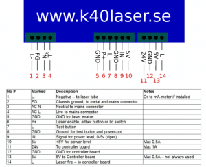
11: Connected to 24V+
12: Connected to 24V-
13: Connected to 5V input
14: Connected to L or LO (depending on controller version)
With external 24V PSU
Remove the cables 11 and 12 from your LaserPSU (blue)
Connect your external 24V PSU to your 24V+ and negative on your controller board.
Take a extra ground cable from your 24V PSU to the ground bolt in the rear, or one of the GND pins on your LaserPSU, number 12 as a example.
Power control wiring
Number 8, 9 and 10 controls your power.
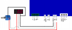
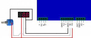
8: Ground to your potentiometer
9: IN – to the “wiper” on your potentiometer
10: 5V to the input on your potentiometer
If you pot goes backwards and lowers power turning it to the right, swap places on IN and 5V on the potentiometer and try again.
Security wiring
If you have a flow sensor, laser enable button, lid switch or other security solutions you want to connect them here.
Number 5 and 6 is the protection. Without a closed loop between these the laser will not fire.
Connect your switch between these pins.
If you have multiple switches, run one cable from number 5 to one pin on the first switch, and from the same switch to the next switch and back to number 6 after the last one. The connection should be made in series.
Cable ferrule crimps are suggested for proper connection.
External power
If you want to install lights, fans or other products to your laser machine always use external power for this. Never connect anything extra to the LaserPSU as this one is on the limit to what it can handle already.
When installing external power, always route a extra ground cable back to the LaserPSU or back to the ground bolt in the rear, you want them to share the same ground.
If you have suggestions or recommendations on other wiring guides – let us know in the comments.

What type of silicone or sealant do you recommend when changing the tube?
Pretty much any silicone that does not cure by acid, or acid curing. They smell like vinegar.
RTV silicone or some kind of 2 component will do it.
Depending where you live in the world they are marked a bit different, but mostly “neutral cure” is the most common. Sometimes marked as Oxime or Alkoxy.
You can also look at “silicone conformal coating”, but most of them are made to just brush on – not fill a void so check it before buying if you go that route.
Hi HP, I just upgraded my K40 to a Trocen AWS 7813. everything looked good until I tried to pulse fire my laser using the appropriate “botton” on the screen. The laser fired but when I let go, would not stop firing.
I had used one wire to connect wire 5 and 6 as they were previously wired to to a red toggle switch labeled “laser” on the K40 Control Panel next to the Green toggle switch labeled “lights.” Then, I disconnected this bridge wire, and the laser won’t fore at all.
Everything else seems to be working fine. Do you have any ideas on what the problem may be?
thank you.
PC
There is 2 solutions to connect the fire/test button on a trocen, hi or low.
You are using wrong one, change to the other and it will work.
Hi = fires when power is added
Lo(w) = fires when power is missing
I dont have a manual or schematic here now, but if you look on google you can find this.
This has probably been asked numerous times but I cant find the answer, I’ve completely ripped out my digital panel and gone with mah meter and pot, going to install a three way switch for pwm control if needed. Nearly done but stuck and at my witts end with searching, what I want to do is install a 12v red halo led momentary push switch for my laser test, I want the led to either stay on or light up when pressed, I also want to install the same switch but latching for the laser on, I can’t work out how to wire the led power as it’s 12v,I have a separate 12v supply but unsure of what voltage goes into the laser test and what goes into the laser on I know one cable is to ground but totally confused I’ve attached pics of the two switches and my power supply,
If I power the switches with 12v it obviously pushes 12v out, I have DC to DC buck converters that I could use , would this work and what voltage does the 12v need to be dropped to for laser fire and laser on.
I just cannot work out how to wire this, I’m happy worrying the switches in different configurations no / nc but can’t work out that I need a power in to the switches and this pushes power out.
I have a similar setup with 12mm buttons, very similar type as yours.
Laser on i use on a latching button – feeding it with 12v for the LED, and the switching side of the button is between GND and P+ on the PSU. (closed circuit will allow beam to fire)
Test-button i use a momentary button – same thing, feed with 12v for LED, but laser on is just a gnd-connection between GND and L (closed circuit will fire the beam)
Just keep the 12v positive and negative away from the latching-side of the buttons and it will work perfect! You should have a pin only for led and not use the “in” part of the button to light the led.
You can test with a multimeter how to do this. Some buttons might need a diode to prevent backwards flow of power to the latching side of the button. I cannot see the schematics of the button you posted though.
Thanks for your reply and help this is the schematic for the latching
I need to check how to do this best, i´ll get back with a suggestion on how to connect it.
This is the momentary, if I used a buck converter to drop the current down would this work, I’m unsure what current the laser on and laser test fire works at
Both laser on and test-fire are closed loops to ground. When the L has connection to GND it will fire. And when P+ has connection to GND it will allow the beam to fire.
So do not put any volts at all to these connections.
I’m new to electrical – do you suggest solid or stranded wire for this guide? I don’t plan on rewiring right away, I have plenty of other stuff to learn, but as I look at different types of wire available at the sizes you mention, I’m wondering how I’d make that call down the line. Solid vs stranded? Thank you so much.
Stranded wire internally, but your local law´s can prohibit that. Most EU countries has rules about stranded wires after the wall outlet, and solid wire before the outlets in the wall. You can probably find your rules and regulations on state or gov. website for electric installations, most countries and states have this.
It´s important to make sure the wire is rated for high power though, either 250 or 400V for high current wires (120 or 230/240V), for the other cables it´s enough with the sizes and most of them are rated for at least 12 or 40V+ anyway.
Hi.
Can you please upload photo of EMI Filter “Chart over the cable kit we just made”. I am not sure i understand the wiring description correctly.
Thanks for a awesome job on this website!!!! 🙂
Best Regards, Morten.
Ooops, it fell out when we re-made the website. I´ll look for the picture again.