Installing a 24V external PSU for your motors and controller board is one of the best upgrades you can do.
The stock power supply (Laser PSU) is not made to take care of both the controller and the stepper motors. We have been talking to the manufacturer and these power supplies was made to have a external power source for the motors and only powering the controllers with the stock PSU. It´s limited to 1 Ampere output, while the motors alone want up to 2A to work properly.
The controller boards in the K40 do not allow for external power to the motors though, so the laser PSU is used anyway for both motor and the controller.
You might have a old 24V brick at home you are not using, just make sure it´s a 4A or more. I would not suggest going above 6-8A just to be sure nothing fries.
What you can expect by upgrading to a external PSU.
– More exact movements.
– More speed and accuracy out of your stepper motors.
– Less problems with your controller board.
Tools you need
– Crimping tool or soldering iron.
– Screw drivers for the connectors on the stock PSU.
Parts you need
– One 24V power supply, 4A is good enough, don´t go below 4A.
– Crimps for joining cables (soldering iron is better)
– Some cables and cable ties or cable sleeves. 0.75mm2 (20AWG) is good enough
Connect your new 24V PSU
Remove the power cable from your laser machine and let it sit at least a hour to make sure the caps are discharged. Just to be safe.
Take a photo of your laser power supply and the cables you have installed. If you unscrew the wrong cables you want to know where they was located, i have done it alot and a photo helps putting everything back.
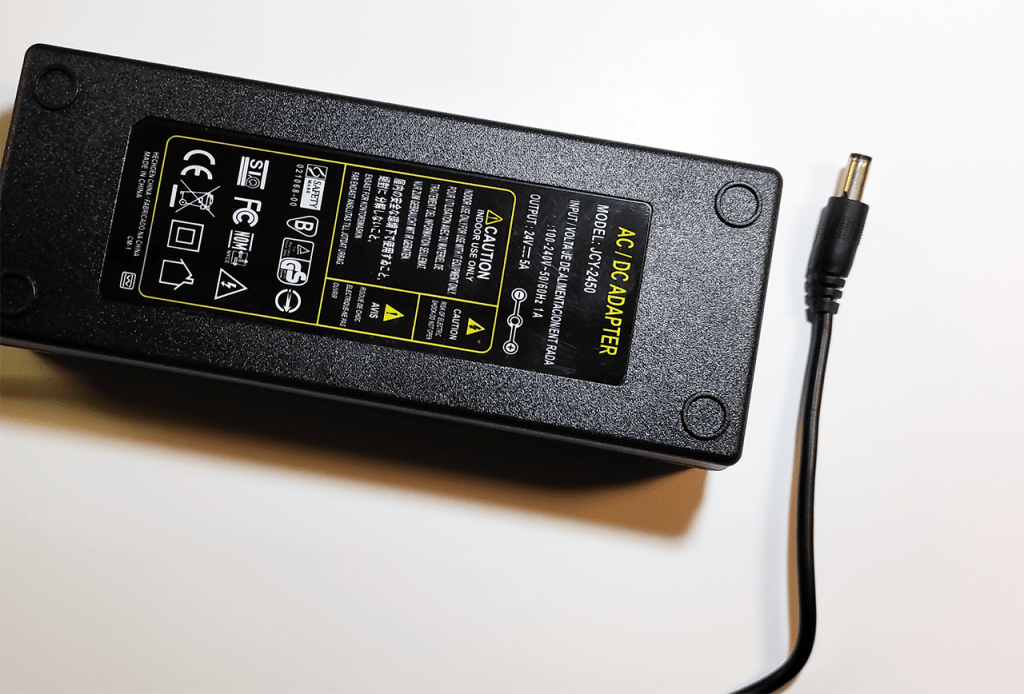
Take your 24V psu, in the picture below you can see how mine looks.
It has a DC jack in one end, we do not want this.

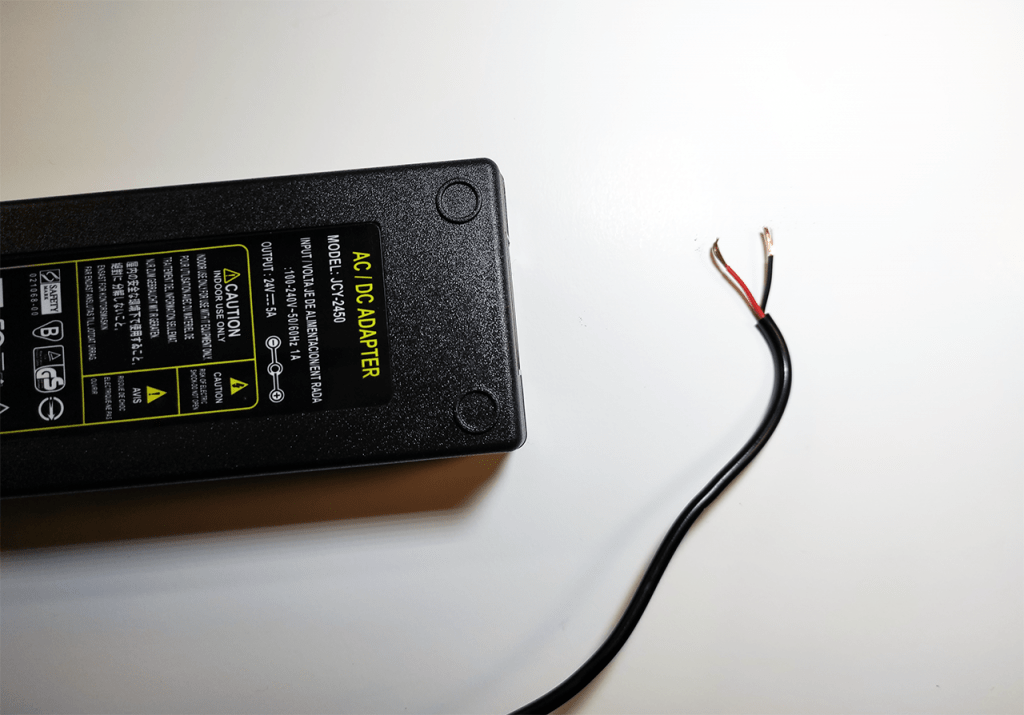
So i cut it off and expose the two wires inside the cable.
Cut the cable as long you need, try it out inside your laser machine before cutting so you have enough.

Now remove the cables from your laser PSU.
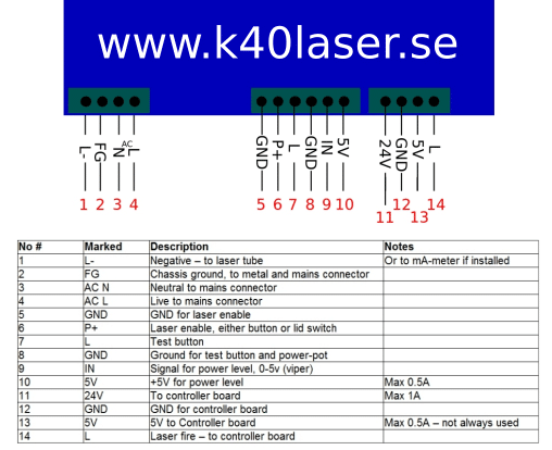
Look at this picture – you want to remove the cables numbered 11 and 12. As can be seen below, 11 is positive and 12 is negative.

The two cables, pin 11 and 12 is going to your controller board – just to make sure you have the right cables, follow them and confirm they are connected to the controller board in your laser machine.
On your 24V PSU – connect the positive cable to the no 11 cable that were located on your laser PSU earlier.
Now you need a bit of extra cable – roughly 30cm.
Solder or crimp the extra cable together with no12 cable to the negative lead on your 24V PSU.
Measure the length needed for the new cable you have – this one goes back to the GND pin (12) on your laser PSU – or you can route it back to the ground pin in the back of your laser machine.
Pin 11 on your PSU is not connected to anything after this upgrade!
More detailed pictures coming shortly, we are installing this in our demo-machine.
You are now ready to tidy up your cables, use zip ties or sleeves to manage your cable routing.
Hello, I have a quick question for you. I am running the Cohesion 3D board in my machine. I am just now getting it all rewired and safe to use. Should I do this mod of removing the 24volt power from the LPSU? The new board is powered by a separate 24v power brick and plugs into the side via a small round power jack. (or you can power the board from a 24v source via screw terminals). I only ask because the board is powered this way to run the steppers and everything from the new brick. But their instructions do not mention removing the wire (pin11) from the LPSU to the new board, they just tell you to plug the harness from the LPSU back into the new board.
Thank you for this website by the way! Great work.
Not sure what pin 11 is on the guide you read. If i suspect its a 5V line and it powers the optical end-stops and is needed. If you upgrade to mechanical switches you wont need it.
But i really need to know what pin 11 is to give a proper reply.
I am referring to the article I posted under. “Connect a 24v external PSU”
I figured replying there would somehow inform you of the reference, sorry about the lack of properly notifying you of the referenced literature. Pin 11 is referenced as a power wire to the original controller board from the Laser PSU. In the article, you mention how to remove that power wire and insert a 24volt power wire of your own into the controller board thus isolating it from the Laser PSU.
I was just wondering if I needed to do that when running a Cohesion 3D board. I have since powered the Laser and found that the Board is not powered by the Laser PSU anymore. I guess Cohesion 3D eliminated that possibility with their design. So I figured it out on my own with a little testing. I was worried about cross-feeding the controller, but I just went for it and did some testing of my own. Thank you for your time.
Cohesion3D has a built in 5v line. Not needed, remove it from the laser-psu.
How important is it that it’s 24,0V?
I’ve got a SP-150-27 Mean Well laying around. As you could prolly guess from the name, it’s a 27V PSU, but the output voltage can be adjusted to between 25,7 and 29,5V
Question: Would 25,7V be too much?
I’m sure I can modify i a bit to get (regulated) 24,0V instead, but I’d rater not ;P
It’s a really good power supply, that can give 5,6A or so, so I’d like to use it 🙂
I have not tried that actually, but in general voltage doesnt matter much if its +2. It depends how sensitive the boards are.
Hello again!
I have 2 questions to go with this crude image I created. I’m numbering them for ease of identification. Thank you so much!
Question 1) Could you tell me if my (terribly drawn) 24v External PSU diagram correctly models your instructions?
—
Additionally, my psu has 2 additional wires shoved into the 24v and GND connections as you can see in my image – those two wires apparently are for a light strip that is mounted in the work area/bed area of the unit.
I’d like to move this light to the 24v PSU (not included in my drawing)
Question 2) Should I wire the light strip parallel to the m2 as it was previously arranged? In other words, could I simply wire the light strip into the new connection points I’m making in the drawing?
—
Thank you again.
I greatly appreciate your help!
Yes, your picture looks good.
You can move the 24V for the lights to the external PSU, or keep it on the LPSU if you want. If the led came with the machine, keep it in the laser psu, it might have some strange noise you dont want. But if not, just connect it to the two points from the 24V psu. Or use a small connection block with multiple outputs.
I still am somewhat lost on what to connect where now. I get a bit confused because you call both power supplies (the built in one and the external PSU, which makes it harder to follow.
Could you draw a quick wiring diagram of how it should look like before and after? Even just a sketch on paper would be a great help as I am apparently a visual learner. (I am aware that the pinning might be different on different machines, but seeing it in conjunction with the explanation would be great.)
Also, I think you are the only one who explains this upgrade, at least that I found on the internet. Most people just stuff more and more consumers into the already overused PSU.
Thanks for this website anyways, it motivated me to get my own K40. It should be here in a week or two, and I already have a bunch of upgrades lined up.
Add your email to the notify box on this link, and you´ll get a notification on new articles. It´s coming a better 24V installation guide shortly with pictures and diagrams.
https://k40.se/k40-laser-buying-installing-upgrading/
If you don´t want to wait for the new article, i have edited this one to only mention 24V PSU or Laser PSU to keep it apart better.
More pics and schematics coming in the new article shortly.
Just so I get this right in my head. By wiring it up like this, I alleviate all the power consumption from the original laser PSU that uses 24VDC, except the tube itself obviously.
So, the board, the steppers, the built in LED lights and the but in Fan will run off the additional 24V PSU? (Given that I take all cables from the 24V slot and move them. Or should some of them stay hooked on the original Laser PSU?
I am planning on just using a 24V 10A power brick, to also hook up some chassis fans and smoke assist fans and integrate all of that into a better control panel.
Oh, and a further question, do you think not would interfere with anything if I just removed the pre installed fan in the back to hook up my better system. (My laser had the latest update in venting, where they installed a better fiting fan and hooked the cables up already, so it’s not plugged in the outlets in the back as it used to.
Speaking of them… Could I also disconnect them, as I already switched the pump to a real wall plug, I don’t see their use, but I’m afraid disconnecting them might interfere with something else
Sorry for the flood of questions
Cheers and all the best.
Correct, move everything to the external 24V psu. Leave the 24V output on the LaserPSU with nothing connected. Leave a GND between the LaserPSU and the external 24V PSU, or use the ground bolt in the back.
Some has commented that we should have a small resistor on the 24V to have a fake load on it to prevent it to break – i have multiple machines without a resistor, and one with a resistor. No difference between them, they all work.
Removing the fan in the back will just make things better, it´s very big gaps on mine and the efficiency is the lowest quality fan they can find. The picture you sent earlier of two inline fans will do the job much better. Print a adapter, or send me a mail at help@k40.se and i´ll send you my template.
Never ever ever use the outlets in the back, i´m removing the ones i got in the machine we bought for articles. Heard many reports of users hooking up the pump there, and then falling out in the middle of a job and blowing the laser tube due to no cooling. I dont think it´s allowed by EU law to use the machine as a power distribution either. Cut the cables and make sure to add some end caps on the wire if needed.
I use a power brick behind the machine, one button starts everything.
Hello! I know that a lot of people faced the same problem on K40, but no one says how to solve it. It seems to me that a part of engraving on acryl is translucent. Does you know what the problem is and how to fix it? Or is the reason in the M2 nano controller?
Is this the same design? To me it looks like the power or speed has changed between the areas.
Some difference can appear due to if its cast or extruded acrylic, but it should not be a clear line like that.
This is repeated on different models, on different materials (including wood). I found a similar problem with most K40 owners in the Facebook group. I checked: the ammeter readings are stable over the entire engraving area. I do not know what to do:(
Is it always the same length of good quality and the rest is bad, or is it shifting where the bad starts?
Have you tried both CorelLaser and K40 Whisperer ?
Always different. I only worked in the K40 Whisperer. But I know that people have a similar problem even in Meerk40t
It might be a controller issue. Have you tried with a different USB-cable? and make sure you use it direct on the computer and no USB-hub between.
Also, remove all other USB stuff connected to the computer to prevent error corrections.
How is your coolant? the state of the lasertube can change depending on the water temperature. Try to keep it steady at roughly 15C with frozen bottles or similar, also check so the flow is good.
Either the usb is full of data so the controller struggles with it – or the laser tube is affected by temperatures, one of them two.
Measure the water before you start, and when it starts to make bad engraving to see if you can notice a temperature difference.
I don´t do much engravings so i have never seen it myself. I do run upgraded boards in all my machines though.
Another thing to test – slow down the engraving to see if you can delay or advance the bad engraving surface.
I have not tried using the new USB cable. After all, the computer does not control the laser power, which means that the engraving must be good throughout the entire area. On the other hand, the computer controls the speed, but the time it takes for the laser head to travel through the “bad” and “good” sections is the same. The water temperature is about 16-20C. But the engraving at the beginning can be translucent, and after 3 minutes it becomes good (I think during this time the water temperature cannot change)
Or am I wrong about something?
Measure the water until you are sure 🙂
And slow down the engraving, some users think its possible to run a K40 at 350mm/s… it´s not, it will just go slower – this might be a key issue too for some.
Try engraving at 100, 150, 200mm/s and see if you get any difference.
And check the water
I engrave at 150mm/s. Okay, I’ll try. Thank you so much.
Personnally, the original USB cable was failing my engraving, I changed it and haven’t any problem (it was communication problem between computer and mainboard)
Thanks for sharing.
Two questions: is the positive at 5V left as it only powers the electronics of the nano board?
Do we put the power supply 220V of the supplementary PSU supply under the same button switch of the K40 so that they turn off or start together?
I have them on a separate 220v connection to a power brick, that brick turns on everything – the laser machine, 24V and the pump. With this setup i never forget anything.