Does your K40 grind and causes noise when homing?
When you turn on your K40 laser machine it´s default setting is to home to top left corner and stop.
It happens that the machine starts to bang against the fence and it sounds like a grinding noise – it´s the belt jumping on the the drive pulley.
For some errors you can also see it moves to top but then suddenly starts to move to the right very slow. The cause is the end-stops for both situations.
If you have a external 24V power source for your controller board and stepper motors, make sure to power them on at the same time when starting the machine. Thanks to Eric noticing this in the comments!
The reason is actually pretty easy.
On both axis there is a optical end-stop with a metal tab, when it comes in to position the movement stops.
It´s also from this position the machine can calculate where the head is in the machine so it doesn’t run too far right or down.
How to fix it
Make sure the metal pieces are inside the optical end-stop in top left position.
If they are, check all cables and remove the optical end stops and inspect them. It happens that solderings are bad and cracks with time.
I suggest changing to mechanical end stops – article how to do this is being written right now.
Here is the Y-axis end stop circled with red.
Here is the X-axis end stop circled in red.
Located behind the laser head.
I have this same problem – carriage moves to top left when I power on but doesn’t stop. The optical sensor bars are in the correct place but obstructing either of them makes no difference. Also the PC cannot see the laser so doesn’t load the driver when connected.
Check the 5v feed to the end-stops. Follow the cables from the controller, make sure the connectors are seated properly and measure with a multimeter on the connector with the end-stop if you have voltage to it.
The PC cannot see the board until a couple of seconds after start, if you start it and have to turn it off due to it not stopping its not enough time.
I think it will be sorted when you solve the end stop issues. Check voltages to the end-stops (5v) and make sure all cables are in good condition and all connectors seated properly.
Thank you for this advice. How do I check this please? There are the 4-wire cables (red/green/yellow/black) that power the stepper motors and the thick ribbon cable The sensors each have 4 soldered pins – 2 on each side. I disconnected the motor power by unplugging both the 4-wire plugs, so it is quiet and not moving. I do not detect any voltage going to any of the 4 pins on either sensor. With the laser still on the pc still hasn’t detected it. Might the controller be caught in a loop? Thanks again for your help.
If possible, take a photo of your controller board so i can see how everything is connected. There is different approaches from the manufacturers and due to this different solutions how to solve it.
You can upload the picture here in a comment.
Here is the board. It is an m2 nano with ribbon connection for the Y axis.
I have seen all pics, pretty standard setup.
I would try with removing all end-stops and use the extra connector on the board and just use regular limit switches (non powered) and convert it.
You can try it without new limit switches, disconnect the two optical switches and start the machine – it should not move at all, and the computer should find it.
See post below: it looks like the y-sensor has failed. Is it possible to buy a replacement y-sensor daughter board? Are there detailed instructions anywhere as to how to do this? I’m afraid I don’t understand much of the rest above – “extra connector?”, “regular limit switches?”, “disconnect the two optical switches?”, etc. Sorry but I am new to this so these terms don’t mean much. Are you suggesting I de-solder the sensors off the boards, or something else?
Start with the Y-sensor. Re-solder the solder points on it and see if it jumps to life. Just add some small amount of solder to it.
That has helped many users with similar issues. The boards are really hard to find so most people convert it to mechanical instead of optical switches. Me included.
Sadly that didn’t work. I get 4.2V across the resistor and LED side, 0V across the sensor side – with and without a metal blade. I have ordered some TCST1030 sensors so – hopefully – can de-solder it off the board and replace the Y sensor.
TCST1030 successfully removed, PCB ok ready for replacement when it arrives.
Does anyone sell these whole boards with sensors, or where to look in general for K40 spares?
Nice work, if you remember please update here if you solved it.
I´m also working on a guide how to convert to mechanical switches coming out next week if you cant fix it.
I think I may have found the cause of the problem. The Lihuiyu Nano M2 board has two sets of connectors various of its inputs and outputs. In particular the ribbon cable on its bottom left that carries the X and Y end-stop inputs and the X servo output has a separate X-servo output socket immediately next to it and then a Y-servo output socket and then the power input in a row along the bottom. On its right side – I now discover – another socket with X and Y end-stop inputs, with GND to either side and a 5th pin for 5V. This is immediately below the board’s serial number. On my board – now that I have removed it – I discover someone (previous owner) has linked together 4 of those pins, so the X and Y sensors are permanently pulled to GND by a line of solder. I am guessing this is why the Y sensor is always at 0V. The X-sensor works. I don’t see how, unless the solder joint is bad. What I can’t figure is why someone would do this? It doesn’t appear in any of the instructions and – on the face of it – seems just to sabotage the machine. Any thoughts?
Cant really see any good use of that fix. It might be that they had other end stops earlier or didnt use the end stops at all and manually stopped or something.
Sometimes other peoples fixes are not really fixes 🙂
They might have used proximity sensors or mechanical switches with that board and used the output on the board you found, and used it without the voltage. Then a constant gnd = engaged end stop.
Problem fixed. It wasn’t actually soldered. It was a drip of solder that had fallen into that socket – possibly when it was made or during some subsequent maintenance – and had become wedged in there and was shorting out all the pins. It pinged out with a fine screwdriver. All voltages now register correctly. Will reassemble and test. If nothing else a good learning exercise in how to understand how the machine works and what its various bits do!
To confirm: machine now reassembled, operational, homing correctly, initialized to the computer and responding properly. Now to start actual testing…
Sweet, good luck!
I removed the K40 y-stop daughter board from the carriage so I could test the voltage on the pins in the ribbon cables. My understanding is for the main 12-way ribbon pin 7 is GND and pin 10 should be 5V. This also should output to the smaller 6-way ribbon with pin 2 as 5V and pin 4 as GND (assuming I have numbered them correctly). I tested these pairs of pins and got between 4.17V and 4.24V across them – varying slightly by time but always the same for both pairs.
Voltages seems fine up to the small board. Some has saved it by resoldering the points on it.
Across the resistor I get 1.81V and across the other two pins of the detector, closest to the 4-pin stepper plug, I get 0V in both directions, regardless of whether the detector is blocked with a card or not.
You need metal in the optical sensor to trigger it.
If you dont see a difference with metal, your end stop is shot. And that is very very common problem with these machines.
OK I think we have progress: I put a metal blade in each sensor manually and tested the voltage across the sensor pins, with 0V on the inside pin in each case. The x-sensor jumped from 0V to 4.8V each time the blade was inserted. The y-sensor remained at 0V.
Thats good, the sensor works. Not the Y-sensor though.
I also checked the power feed to the controller board. As I understand it pin 2 is GND, pin 1 is 24V and pin 3 is 5V – these are all correctt. Pin 4 is referred to as LO and registers 4.6V. I don’t know what this is for.
LO is the power setting, should be 0-5V depending on power set on the potentiometer or digital panel. So 4.6 is no problems.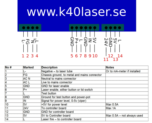
But you should only have this when firing the laser, not all the time. So double check that one. It should be connected to pin 14 on the power supply.
See picture here:
First of all, thanks for all the information you share here, it’s been really useful.
I have an issue and I was hoping to get some info before I replace the controller. My machine homes correctly on the Y axis, but the X axis behaves erratically and never gets anywhere. If I manually move everything to the top left the movement stops, so the end-stops seem to be working.
I’ve also disconnected the motor and connected it directly to the controller instead of using the flat cable that carries both the X signal as well as the end-stop signals, and in that case the motor moves correctly.
Is this a common problem, or something completely random?
Thanks in advance!
If you can run it directly without the flat cable i would say this is the issue. The small board it connects to fail often. You can try to fix it by going over all solder points with a soldering iron, but its better to run direct cables to the motors from the controller and replace the optical end stops with mechanical.
Thanks for your answer! I’ll try to run direct cables to see what happens then, I’ve been suspecting that small board as well, but it seems so simple (just bridges and a single resistor) that it doesn’t seem possible for it to fail.
Thanks again!
mechanical end stop not working, need to know what to buy to replace on a K40 laser engrver
If you have mechanical end-stops, you can replace them with any switch with 3 pins. Check ebay, amazon or similar for “micro switch” and find one that is similar to the ones you have installed.
mine are a 6 pin, i got a 3 pin one but not sure how to install them.
Send a picture of the ones you have installed to help@k40.se and i´ll have a look.
they are the ones that came with the machine, i will try take some picks for you
Some machines are wired different and if i tell you to connect the end-stops the default way, i might cause problems or destroy something on your machine. So it´s better with pics 🙂
sent them over for you, as best i can get photos of them
In my case, the homing didn’t work properly for a different reason. When I switched on the power, the laser head only moved a bit to the right and down, and quiet slowly. The reason turned out to be that I was switching on the external 24V power supply I added to the machine, which was powering the board and motors, but not the original 220V power supply for the rest of the machine. The 220V needs to be on before or at the same time as the 24V for homing to work.
Thank you for sharing your experience! Good information.
This happens when the end-stops doesnt get signal, it starts to move to the right and other crazy directions.