Want to convert your machine to analog instead of digital?
The digital panel is stupid, it´s made for 40-100w machines and needs to be calibrated, so 100% power actually is 100% on your 40w. The sellers often just buy parts and put together and forget this, your output will have 100% power anywhere from 60 to 100% on the panel.
Always combine your digital panel with a mA-meter. If you dont have one – check out this article how to install one.This guide will upgrade your digital panel to a enhanced power controller with a small digital meter. There is no quality or power difference between the digital or the analog setup, the analog is a bit easier to use.
Prerequisites
Follow this guide to make a upgraded version of the potentiometer setup. You need this one to complete the conversion.
Tools you need
– Wire stripper and cutter
– Screw drivers
– Wire, shrink tube or insulating tape.
– 0.75mm2 cable (22AWG)
Parts you need
– Potentiometer, or the enhanced pot. version.
– Two push buttons, one momentary, one maintained. (for laser enable and test fire)
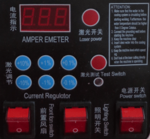
This is the layout of the most common digital panels. It may be different color.

Depending on what functions you want later you might want and what your laser is equipped with you might need to save the buttons and incorporate in your panel.
Step by step
Preparations
Start with removing all power cables to the machine and leave it alone for a couple of hours.
Removing the old panel
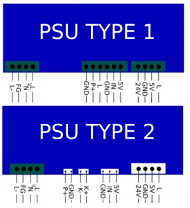
Start with opening the lid to your laser machine and inspect the Laser PSU (power supply) which type you have.
Here is the two most common types, there is two more uncommon ones but the markings are similar so you can still use this guide.

Removing the old cables
For PSU type 1
Remove all cables from GND, IN and 5V pins located close to each other – verify before removing that these cables are located to the digital panel.
If you have other cables you need to identify where they are located on the PSU to identify what they do. Some manufacturers use other pins than these three for the panel. If you are unsure – ask in the comments below.
You might have a Laser ON and/or Laser Enable connected to GND and P+. Remove both of them if they are located on the panel.
Check out this article to a guide for re-wiring your laser-machine to identify the connections from your LaserPSU.
For PSU type 2
Remove all cables coming from the panel, normally its a 3-pin and a 2-pin connector. Save the cables because you need them later for splicing the new setup.
Installing the new potentiometer
For PSU type 1
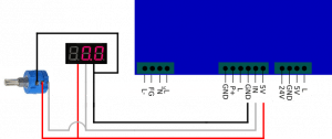
Install the new potentiometer as shown below. This image shows a enhanced potentiometer upgrade but you can do the same with a regular potentiometer without the volt-meter. Read more about the enhanced potentiometer here.
For a laser test-button: Use pin L and GND located to the left of the cables to your potentiometer. You can share the GND.

For PSU type 2
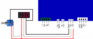
Use the old cables from the digital panel with the connectors, cut them and splice/crimp the new cables you have from the new potentiometer.
For a laser test button: Use pind K- and K+

For both types of PSU
For a laser-enable button: Use pin GND and P+.
I recommend using a 10-turn potentiometer for easier power setup. If your pot goes backwards, swap the gray and 5v cable (gray and red) on the potentiometer.
If you have a lid switch, or flow sensor you need to install this in SERIES with the laser enable switch. If you use both lid switch and flow switch they all need to be connected in series.
Testing your setup
It´s time to test-run your connections.
Put back the power cable and fire up your laser machine.
Try the test-fire button first – you should see the laser tube firing as long you are holding the button.
Also try the potentiometer for different power levels, check the mA-meter with the test-button so it moves the correct orientation, turning to the right increases the power.
Replacement panel
When removing the old panel you maybe want to replace it with a better fitted panel for your machine.
Here you can download a ready made panel for the K40 laser machine, and one blank to design yourself with the cutouts you need.
– Basic panel for standard K40 setup with hole for mA-meter, potentiometer and two buttons.
– Empty blank panel

Nice and clear, congratulations. How about adding a led which shows when the laser is firing? Not only when hitting the test laser button of course !
Thank you. A red dot or cross is what i use on all my machines with the upgraded laser head. There is a free bracket to download with a LED-holder if you need one on the download-page https://k40.se/downloadable-files/
Or do you mean just a indicator on the panel? That is good idea, i have aluminium buttons in my machine which lights up when the laser is enabled so i know it can fire.
Yes I was talking about a led on the panel which lights up when the laser is firing. An idea where/how to branch that led? K+ and K- won’t work. GND and P+ won’t work too since it performs the laser overall ON/OFF.
Any suggestion?
It can work on K/L pins, it´s a “ground”/low level input. If you add a LED from the 5V+ with a diode and resistor to prevent any strange things on the K/L it should light up when the laser is firing.
But, not sure if this interrupts the firing signal or something, i have never tried it.
Need to be researched a bit more!
“For a laser-enable button: Use pin GND and P+.”
For some reason, I can not get this to work or I’m doing it wrong, if the plug is left open it should not enable the test-fire, or is the test-fire always enabled?
On the PSU with white connectors, a closed circuit between GND and P+ enables the laser tue to fire. If the circuit is open, it cannot fire the tube.
You can test this with a small cable between GND and P+ and pushing the button for test-fire you have connected to K+ and K- or enable it through software. (running a cut or engrave).
Using the test-button on the PSU itself bypasses everything and fires anyway.
Where are the files for the panels?
Sorry they fell out in the latest website update. I have added two now, basic design, use them and add your own buttons or similar. I will add more designs shortly.